EVPN-VXLAN Explainer 5 - Layer 3 with Asymmetrical IRB

Thus far, this series of posts have all been about Layer 2 over Layer 3 models; the customer ethernet frames encapsulated in UDP, traversing L3 networks. The routing has been confined underlay, the customer traffic has stayed within the same network.
No longer! In this post, things start getting a little more interesting, as we look at routing the customer traffic with an EVPN feature called Integrated Routing and Bridging, or IRB.
- First we look at the concept of routing in VXLAN networks.
- Then we have an in-depth look at asymmetrical IRB (I'll be dealing with symmetrical in the next post).
✅ L2 is intra-subnet, L3 is inter-subnet
📥 Intra-subnet
To define terms, when I say 'intra-subnet', that is L2 traffic transferred between nodes in the same subnet.
📤 Inter-subnet
'Inter-subnet' refers to a traffic flow that traverses subnet boundaries.
☎️ The Centralized IP L3 Gateways of Old
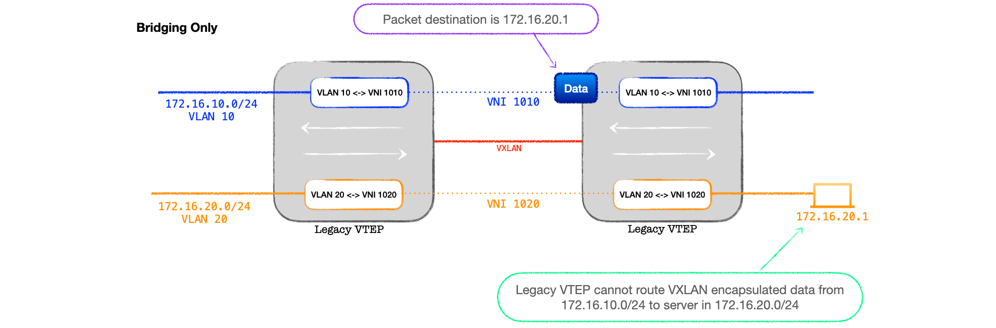
- With VXLAN networks in the past, inter-subnet communication was often performed by a centralized, IP only, gateway on behalf of the rest of the network.
- Traffic from customer-side networks would need to be sent to this central device for routing, which often created inefficient traffic flows, and possibly a bandwidth choke-point.
- Imagine two VMs sat on the same server, but in different subnets. To send traffic from one to another, the packets might need to travel all the way across the data centre to be routed, only to be sent back to the original server. Not exactly good design.
❓ Why? The perennial question
If centralized gateways created these problems, why were they deployed?
The short answer is 'hardware'. With VXLAN, devices need to handle the additional headers used to encapsulate the traffic (VXLAN, UDP, Outer IP, Outer L2). That creates additional steps in the packet handling pipeline on a single device, whether it be encapsulating or decapsulating; the hardware needs to be able to also route, and the boxes at the time weren't able to do this.
🔨 Workarounds, workarounds, workarounds
What then?
Either deploy a physcial cable looped back from port to port (let's not mention that again), or deploy an external L3 routing device.
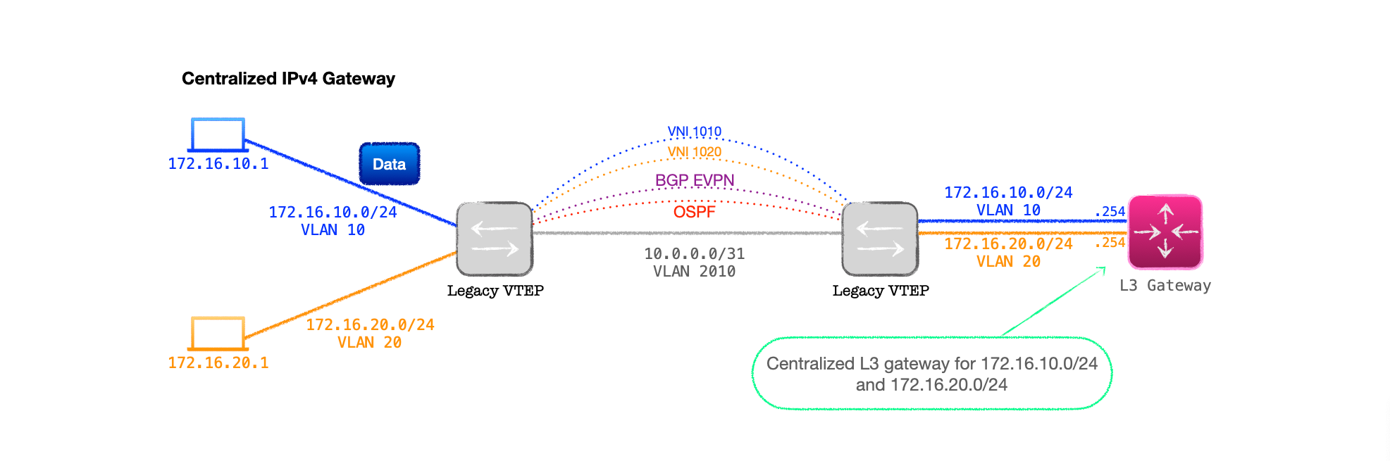
This allows the VTEP to decap and then hand off the routing of the 802.1Q tagged IP only traffic to a standard L3 device. Step forward our centralized L3 gateway.
Design Notes
- The VTEP is connected to the gateway with an 802.1Q trunk.
- Each VNI on the VTEP is bound to a VLAN on the inter-connecting trunk.
- The external L3 device is configured with L3 interfaces for each one of the VLANs on the trunk and acts as the gateway for each VLAN/subnet pair.
- Thus the L3 gateway does not need to be VXLAN capable. It merely routes between subnets and returns the routed IP traffic back to the VTEP for encapsulation on the destination VNI.
While this works, and provided a solution to early hardware limitations, it created inefficient traffic flows, plus the VTEP to L3 gateway link needed to carry all the routed traffic, placing demands on bandwidith in large networks.
💬Note: This was a whole thing back in 2014, which I've simplified somewhat. Just search 'Trident 2 VXLAN routing' for links around 2014-15 if you want more information.
🦖 Hardware evolution
Thankfully, hardware VTEPs evolved, and Aruba VXLAN capable devices, such as the 6300s I'm using, are able to perform the steps required to route between VXLAN networks on a single device, no need rely on a centralized gateway.
Moreover, EVPN-VXLAN has been developed to incorporate a means of routing between VNIs on each VTEP, a feature that goes by the name of Integrated Routing and Bridging, or IRB.
🧱 So why does the centralized model still exist?
Before we dive into the wonders of IRB, we should recognise that designs that utilise a centralized model are still very much in use in today's data centre and campus networks.
The reason for this is, in my experience, often because not only is the routing centralized, but also the security.
A common approach is to deploy a design that centralizes inter-subnet and/or inter-VRF routing and, at this point, firewalling to permit or deny traffic based on the desired security profile as it moves between subnets or VPNs.
If the firewalls in use are incapable of filtered VXLAN traffic, a VTEP needs to sit in front of the firewalls, decapsulating & encapsulating VXLAN, while handing-off 802.1Q tagged traffic to the firewalls for processing.
🔀 Integrated Routing and Bridging
IRB allows the EVPN speaker to either bridge the traffic from a customer-side subnet or route between them.
The bridging part we've covered in depth, that's the L2VNI functionality of my previous posts; now we introduce the routing aspect.
In contrast to the centralized model of Figure 2 above, with IRB we can send traffic from one subnet to a destination in another subnet across the VXLAN network. No more decapsulating the traffic to route via an external device, the VTEPs do the routing for us.
IRB is detailed in the rather recent RFC 9135, which has all the info laid out, but, personally, I found this quite challenging read.
In my attempt to explain IRB I have the advantage of a specific platform to use in my examples rather than just theory, so here goes.
🌉 Bridging recap
As mentioned, IRB is built upon the bridging concepts we've already looked at. In fact, we use a lot of the configuration that we've already covered to build the design.
To recap then, when creating a L2VNI within EVPN we need a number of separate configuration components:
📝 Config Snippet 1: EVPN VLANs
We need to tell EVPN which VLANs are of interest, that is, which ones to record source MACs on via the local learning process.
Here's a sample configuration snippet:
evpn
    vlan 10
        rd auto
        route-target export auto
        route-target import auto
    vlan 20
        rd auto
        route-target export auto
        route-target import auto
📝 Config Snippet 2: VXLAN VNI-to-VLAN bindings
We also need to bind the customer-side VLAN to a VNI, which we do under the interface vxlan 1 configuration:
interface vxlan 1
    source ip 192.168.0.1
    no shutdown
    vni 1010
        vlan 10
    vni 1020
        vlan 20
📝 Config Snippet 3: BGP EVPN neighbours
Next we need to build the BGP peering and activate the L2VPN EVPN address-family:
router bgp 65001
    bgp router-id 192.168.0.1
    neighbor 192.168.0.2 remote-as 65001
    neighbor 192.168.0.2 update-source loopback 0
    address-family l2vpn evpn
        neighbor 192.168.0.2 activate
        neighbor 192.168.0.2 send-community both
📝 Config Snippet 4: Customer-side port config
Finally, we have the customer-facing port to act as the ingress & egress for traffic to and from the VTEP:
interface 1/1/20
    no shutdown
    no routing
    vlan trunk allowed 10,20
🪄 Now to add in some Layer 3
With the configuration thus far, our VTEP is just acting at Layer 2 for the customer-side VLANs, there's no Layer 3 interface for the customer-side nodes to direct their traffic towards for routing. Let's dive into the new stuff and add in the L3.
📝 Config Snippet 5: Customer-side VRF
Now we are adding in L3 for our customer-side networks, we need to keep this separate from the underlay networks.
We do this by configuring a VRF for the customer.
Keep in mind that we are only configuring inter-subnet flows here, traffic will sit in the same VPN across the network. Thus, with only one customer or VPN, we only need a single VRF on the VTEP. Traffic will move between subnets, but will stay in one VRF.
Note that if you have a multi-tenancy VTEP, serving multiple customers or multiple VPNs, then you would configure multiple VRFs.
Here's an example of VRF configuration:
vrf customer_a
    rd 65001:1
    route-target export 65001:1 evpn
    route-target import 65001:1 evpn
🤔 Asymmetrical or Symmetrical Routing?
The next part of the configuration depends upon what type of routing we wish to deploy. There are two types, asymmetrical or symmetrical, which are configured quite differently.
In broad terms, the difference between these two approaches is that asymmetrical requires our VTEPs to be configured with all the VLANs, subnets and VNIs that we want to route between; whereas symmetrical just requires the local VLANs, subnets and VNI, plus a different type of VNI, called an L3VNI, that is shared between all of the VTEPs and handles the routing.
There are pros and cons to each approach, and some interesting details in the implementation.
Due to the amount of information needed to cover IRB and these different approaches, I'm dedicating a post to each one of the designs. This one, as the title suggests, focuses on asymmetrical IRB, so that's what we will now configure. I'll go over symmetrical IRB in the next post.
📚 Asymmetrical IRB Configuration In Detail
- With this approach, the ingress VTEP handles the routing between subnets locally, then forwards the VXLAN encapsulated traffic to the destination VTEP in the destination VNI, so the egress VTEP just needs to decapsulate and bridge the traffic.
- In order for all the routing to happen on the ingress VTEP, it needs to be configured with all possible VLANs, subnets and VNIs that it must route between.
- The egress VTEP just needs to bridge. But, for a successful bi-directional traffic flow, the egress will also play the role of ingress for the return traffic, and thus, all VTEPs need to be configured with all those L2 & L3 components.
📝 Config Snippet 6: Layer 3 interface
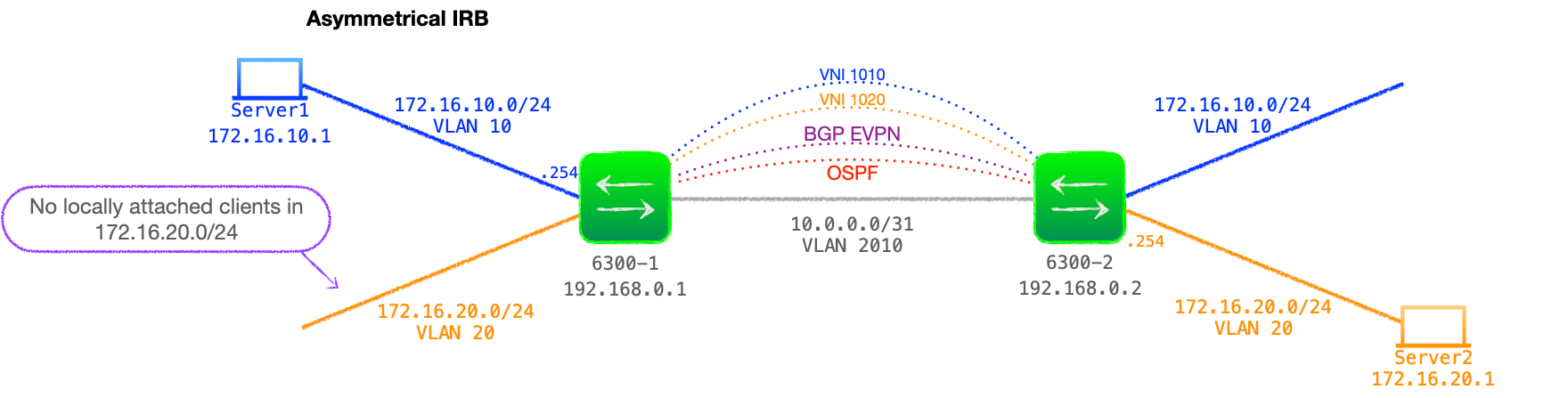
In this design, the VTEPs act as the gateway for the locally attached subnets and, because, this is asymmetrical IRB, each VTEP needs to be configured with all subnets that it must route between.
Thus we must configure our VTEPs with all subnets in the network, regardless of whether there are any local hosts within the subnet.
Also note that, as these are customer-side networks, the L3 interfaces must be attached to the customer VRF:
interface vlan 10
    vrf attach customer_a
    ip address 172.16.10.254/24
Network and Configuration Example
See Figure 3 below for a diagram of the example network we will be working with.
VTEP Configuration Example
Here's an example VTEP configuration for asymmetrical IRB between VLAN 10 and VLAN 20.
vrf customer_a
    rd 65001:1
    route-target export 65001:1 evpn
    route-target import 65001:1 evpn
!
vlan 1,10,20
!
evpn
    vlan 10
        rd auto
        route-target export auto
        route-target import auto
    vlan 20
        rd auto
        route-target export auto
        route-target import auto
!
interface vlan 10
    vrf attach customer_a
    ip address 172.16.10.254/24
interface vlan 20
    vrf attach customer_a
    ip address 172.16.20.251/24
!
interface vxlan 1
    source ip 192.168.0.1
    no shutdown
    vni 1010
        vlan 10
    vni 1020
        vlan 20
!
router bgp 65001
    bgp router-id 192.168.0.1
    neighbor 192.168.0.2 remote-as 65001
    neighbor 192.168.0.2 update-source loopback 0
    address-family l2vpn evpn
        neighbor 192.168.0.2 activate
        neighbor 192.168.0.2 send-community both
    exit-address-family
Config notes
- The customer-side networks are placed into the VRF 'customer_a', note the 'evpn' specific route-target configuration command.
- This VTEP only has local hosts in the VLAN 10 172.16.10.0/24 network but must be configured with VLAN 20, an L3 interface in 172.16.20.0/24 and bound to VNI 1020.
- Configuration examples for L3 IRB often have the VTEPs configured for an additional feature called 'Distributed L3 Gateway'. AOS-CX supports this functionality but I've chosen not to use it here so as to limit the number of new concepts I'm introducing at once. I will go into detail about this feature in a later blog.
🚶 Asymmetrical Walk Through
With many different networking processes working together to achieve IRB, it can be a tricky topic to really grasp. Taking inspiration from the RFC, here's a walk through of the steps that comprise asymmetrical IRB, starting with the set up of the control plane, then the data plane.
🕹 Control Plane
Base line
- To start, both 6300-1 and 6300-2 are fully configured for EVPN asymmetrical IRB as above, with an established BGP session.
- However, both VTEPs have their customer-side facing interfaces shut. Thus they have not learnt any MAC addresses on VLAN 10 or VLAN 20.
- At this stage, the only updates in the BGP EVPN table are RT-3s, that is each VTEP declaring their configured VNIs, 1010 and 1020.
Steps
- We open 6300-1's customer-facing port 1/1/20, setting it to
no shutdown. - With the local link up, the connected node, Server1, sends a gratuitous ARP on VLAN 10.
- 6300-1 records Server1's MAC address in its MAC table, EVPN table for VNI 1010 and creates an RT-2 MAC only update, which is sent to 6300-2.
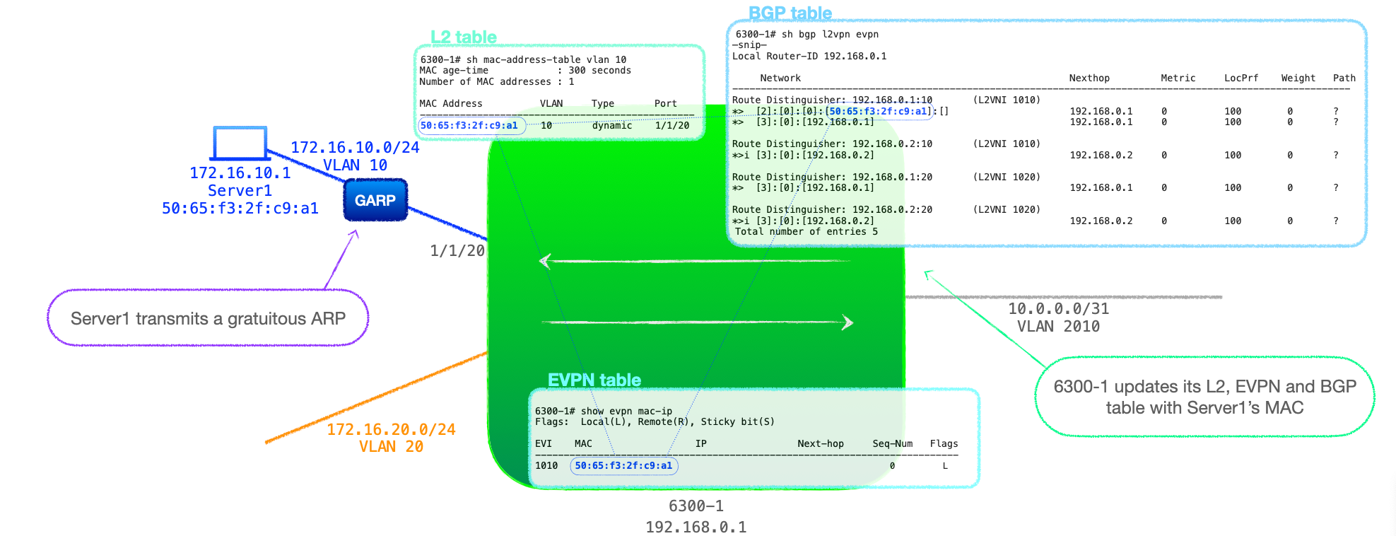
- 6300-2 receives 6300-1's RT-2 and records Server1's MAC in its BGP EVPN table against VNI 1010, with 6300-1's address (192.168.0.1) as the next-hop.
- 6300-2 also populates its EVPN table and its MAC table with Server1's MAC address, listing 6300-1 as the next-hop.
- We now open 6300-2's customer-facing interface and a similar process ensues, Server2 GARPs, 6300-2 records the source MAC and sends an RT-2 MAC only to 6300-1.
- At this stage both VTEPs have entries for the MAC address of Server1 and Server2, but no information about their IPv4 addresses.
- As I want to try to focus on the control plane here, then look at the data plane, let's say that Server1 sends some traffic off subnet. This is not directed towards Server2, it is just some IP traffic that 6300-1 needs to route for it, as Server1's default gateway.
- The off-subnet traffic means that Server1 will ARP for its configured default gateway, 172.16.10.254, 6300-1's L3 interface for VLAN 10.
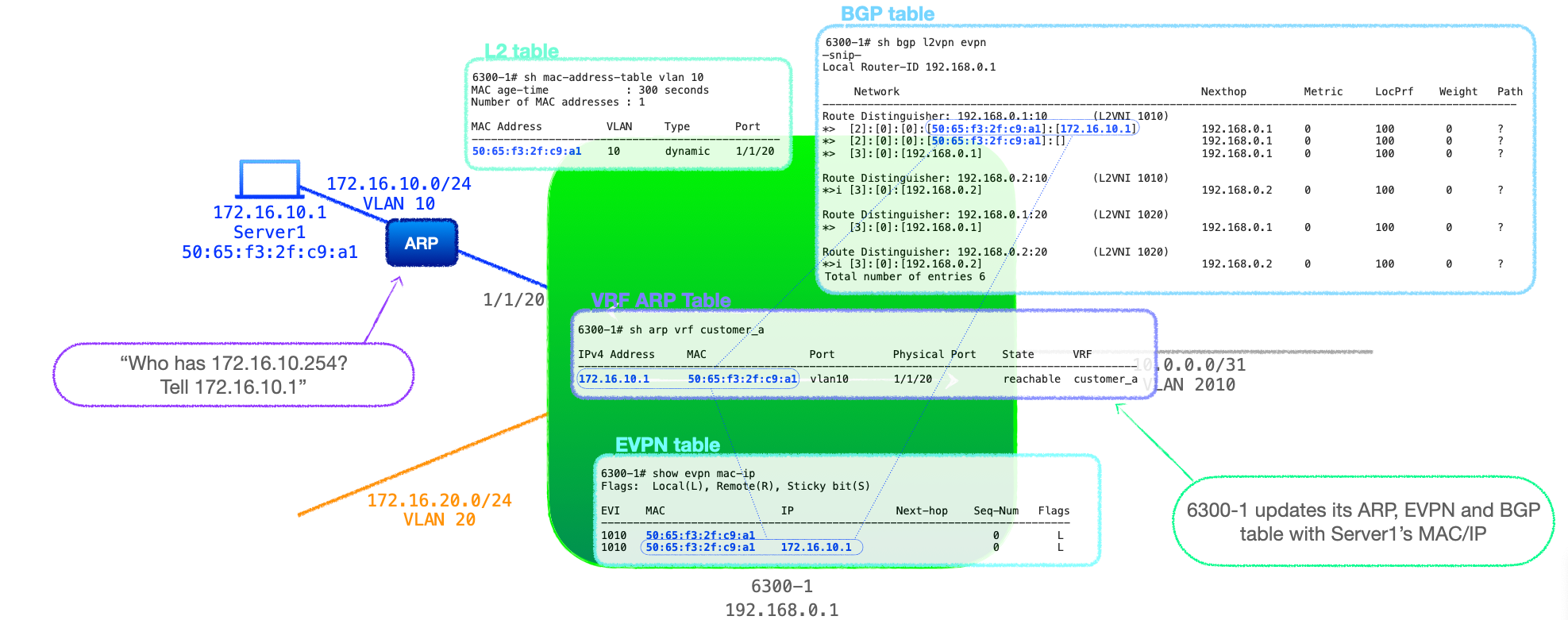
- 6300-1 responds to Server1 with its MAC address. Any subsequent traffic flow is not relevant to this walk-through, the important detail is that 6300-1 now has an ARP entry for Server1 in its VRF customer_a ARP table.
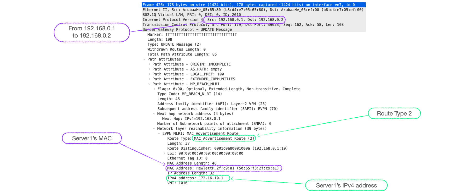
- 6300-1 now adds Server1's MAC and IP as an RT-2 to its BGP EVPN table under VNI 1010, and advertises it to its peer, 6300-2. (If you recall from Explainer 3 RT-2's can carry both MAC addresses and IP addresses.)
- 6300-2 receives the update, checks the route-target and imports it into its BGP EVPN table under VNI 1010.
- Moreover, 6300-2 uses Server1's MAC and IP information in this RT-2 to populate its ARP table. Note that 6300-2's MAC address table already had Server1's MAC address from the first MAC-only RT-2 from 6300-1.
- To ensure we have a fully populated control plane, let's say that, rather fortuitously, Server2 also performs a similar off-subnet traffic flow. Thus 6300-2 can also populate its ARP cache, generate a MAC and IP RT-2, which 6300-1 uses to complete entries in its BGP EVPN and ARP table.
At this stage, our VTEPs have fully populated MAC, ARP, EVPN and BGP EVPN tables (ok, that inclusion of an ARP for the gateway might upset the purists but I'm hoping that makes the data plane, and subsequent look-ups a little more easy to follow).
Asymmetrical Data Plane and Routing Lookups
With the relevant VTEP tables fully populated, let's go through the steps if Server1 tries to ping Server2.
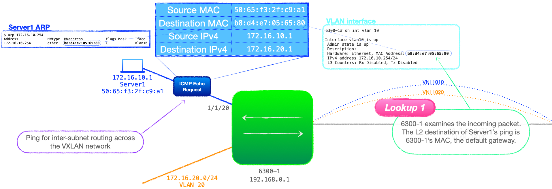
- Server1 sends an ICMP echo request from 172.16.10.1 to 172.16.20.1, and, because this is off of the local subnet, Server1 uses the destination MAC of its default gateway, that being 6300-1.
- 6300-1 receives the traffic, and performs an L2 lookup, which reveals that it is the destination. This is lookup 1 in the process.
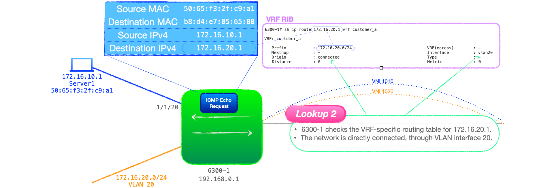
- 6300-1 then performs an L3 lookup in the table associated with the ingress VLAN, that being VRF customer_a. This is lookup 2.
💬This is an interesting point I think, 6300-1 has an entry for the destination subnet, 172.16.20.0/24. Remember that, with asymmetrical IRB, the VTEP must be configured with an interface in each subnet that it must route to. So all the L3 lookups at this stage will be successful, and they will point to locally connected L3 interfaces, in this case VLAN 20.
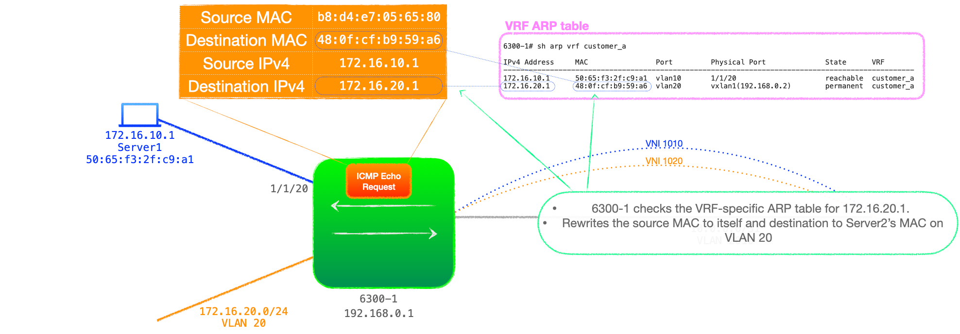
- 6300-1 checks its ARP cache, which includes an entry for Server2's IPv4 and MAC address. 6300-1 now rewrites the source MAC address to its own MAC address for VLAN 20 and the destination MAC to that of Server2's, according to the ARP table.
While this sounds like an additional lookup, the RFC does not list it as such because: "References to a host IP lookup followed by a host MAC lookup in the context of asymmetric IRB MAY be collapsed into a single IP lookup in a hardware implementation."
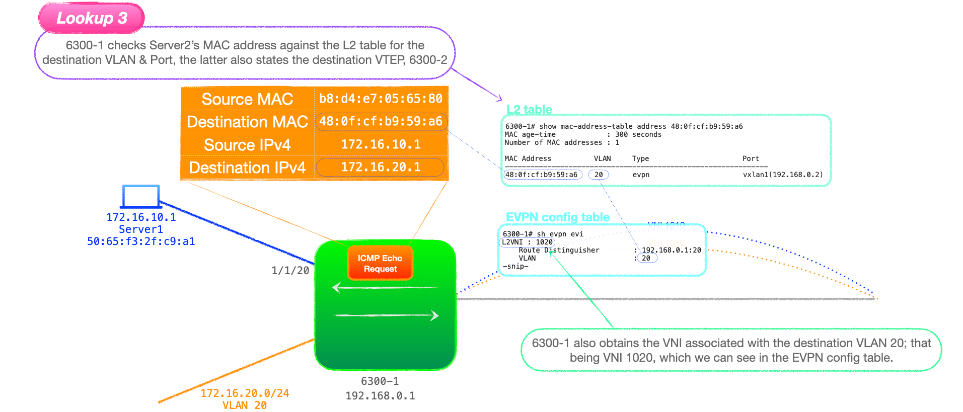
- 6300-1 now checks the MAC address table for Server2's MAC. This is listed as learnt via EVPN, with a next-hop address of the VTEP advertising this MAC, that being 6300-2 with the address of 192.168.0.2. This is lookup 3.
In addition, as part of lookup 3, 6300-1 will also obtain the destination VNI, that being 1020. We can see this is in the EVPN config table ,show evpn evi.
-
With all the necessary information gathered, 6300-1 encapsulates the data and unicasts it to 192.168.0.2. Note that the ping has now been routed and is sent marked with the destination VNI, 1020.
-
6300-2 decapsulates the packet addressed to itself, checks the VNI and performs a lookup for Server2's MAC address in the VLAN associated with 1020, that being VLAN 20. This is lookup 4
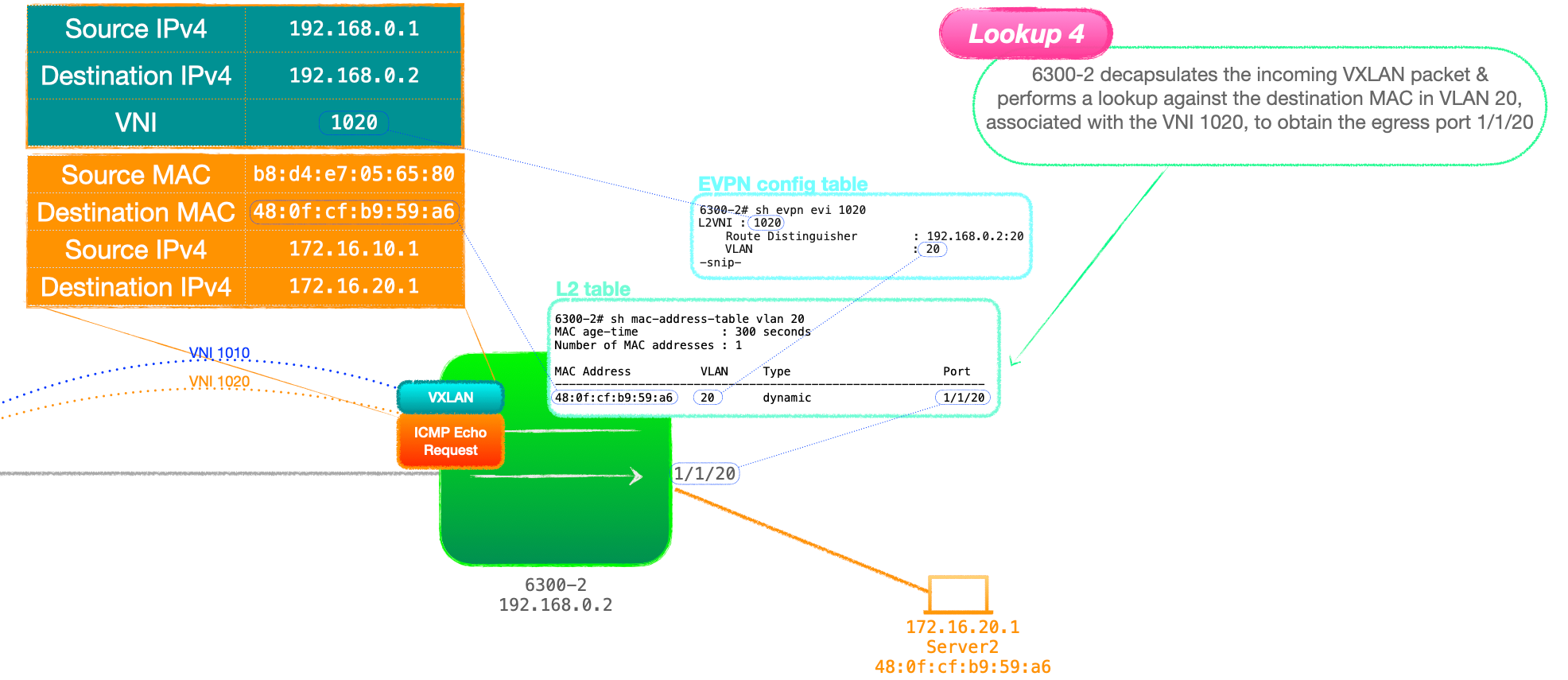
- 6300-2 forwards the packet out of the physical port listed in its MAC address table for Server2's MAC, 1/1/20.
- Server2 receives the ICMP echo request and replies.
- This process then plays out in reverse, with 6300-2 routing from VLAN 20 to VLAN 10 before encapsulating the traffic for transport across the VXLAN network.
Once Server1 receives the ICMP echo reply, we have ourselves a successful ping. ❗️❗️❗️❗️❗️
🔬 A few observations
-
That's obviously a lot of steps and a number of processes working together to service our humble ping.
-
There are numerous tables and lookups, with MAC address, BGP, ARP and RIB in play.
-
I should also caveat this by sayin that I've included each step separately for illustrative purposes. With modern hardware, certain table lookups will be combined and not sequential but I hope this gives a roughly accurate run through.
In addition, here's a few things that I think are worth focusing on:
1. Ingress versus Egress VTEP lookups
- The ingress VTEP performs the initial L2 MAC lookup (1), the routing between subnets (2) and another L2 lookup before encapsulating the traffic (3).
- The egress VTEP just does an L2 lookup on the MAC in the destination VLAN (4).
2. Why it is called asymmetrical IRB?
Hence why this is called asymmetrical, the ingress performs a MAC then IP then a MAC lookup, while the egress only performs a MAC lookup!
3. RT-2 to update ARP cache
- RT-2 UPDATEs with MAC & IP are used to populate the ARP tables of remote VTEPs.
- However, I'm guilty of tweaking the process here a little, if the end client servers had not sent off-subnet traffic, the local VTEPs would not have an ARP entry for the servers. It is highly likely that the VTEPs would have MAC table entries for the clients because the servers send gratuitous ARP on link up, but not ARP entries.
- But, in this case, the ingress VTEP can populate its ARP cache by the regular means. Remember that the ingress VTEP has an L3 interface directly connected to the destination VLAN, VLAN 20. The VTEP, if it has no ARP entry for the destination IPv4 address, will send an ARP request out of all VLAN 20 ports and all VTEPs associated with VNI 1020, the VNI bound to VLAN 20.
- Thus, the ingress VTEP can resolve ARP for the customer-side destination.
Closing Words
That's it for asymmetrical IRB. There is a lot of detail here, but I hope it is digestible.
In the next blog, I will look at symmetrical IRB.
Thanks for reading.
🐦@joeneville_
💬Final note: There is so much in here that I've no doubt there are typos and errors, if you see anything glaring, please let me know via twitter or joenullzero@gmail.com