EVPN-VXLAN Explainer 6 - Symmetrical IRB

Now let's continue our look at routing with EVPN-VXLAN as we focus on symmetrical IRB.
This post is essentially building upon a lot of what we covered in the previous post. So, if you haven't read that yet, please do, then meet me back here. This post will make a lot more sense if you do.
🔬 Symmetrical IRB in Detail
While symmetrical and asymmetrical IRB have the same functional outcome; to route inter-subnet traffic, there are a number of major differences in the requirements and configuration of each.
Most notably, symmetrical IRB frees us from the requirement to configure all VLANs & L2VNIs on all VTEPs.
Here's an overview of the features and components that we'll be covering:
Symmetrical IRB Architecture Notes
- Symmetrical IRB offers a more scalable approach to routing VXLAN traffic because VTEPs are not required to have knowledge of all destination clients, they do not need to hold an ARP cache entry for a destination, unlike asymmetrical IRB.
- VTEPs are only configured with the VLANs, subnets and VNIs that host locally connected clients.
- To ensure successful end-to-end connectivity for inter-subnet traffic, a number of new requirements and features are deployed with symmetrical IRB:
- A L3VNI for routing - this is a special type of VNI, specifically for Layer 3 routing. It is configured on all VTEPs in the networks. Inter-subnet traffic is encapsulated with this VNI as it is sent across the VXLAN network.
- 'EVPN Router's MAC' - a new BGP extended community, carried in EVPN updates, to identify the egress VTEP (see Config Snippet 4: Virtual-MAC address below for more details).
- A new Route Type, RT-5 - used to advertise IP Prefixes (see Config Snippet 2)
That's a lot of information to take in and plenty of new features to examine, so let's dive in.
Example Network
Here's the example network we will use to demonstrate symmetrical IRB and inter-subnet routing.
Please note that it is minimal on purpose, I will expand on this network example where necessary.
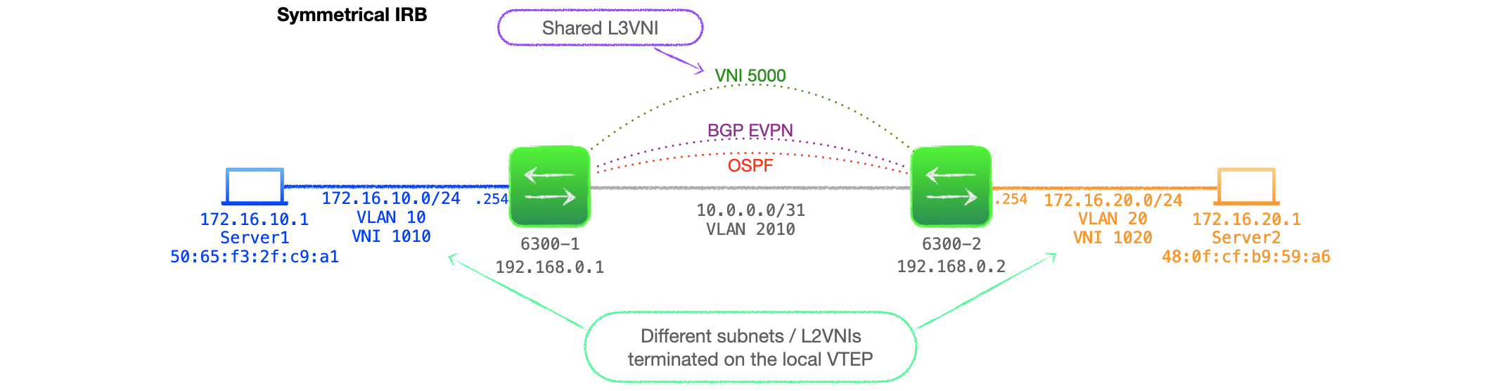
Network Design Notes
- Each VTEP is an Aruba AOS-CX 6300.
- The VTEPs are only configured with the VLAN, subnet and VNI that host local clients, they effectively act as the termination point for each.
- VNI 5000 is a share L3VNI used for routing.
- No L2VNIs traverse the L3 core.
Symmetrical IRB Config
Baseline L2VNI Config
Let's start with a base config for one of the VTEPs.
- Symmetrical IRB uses L2VNI, which we've already covered in depth.
- Our baseline is the config for 6300-1, with an L2VNI 1010.
- We will then add in the new configuration to enable us to route and ping from the local host 172.16.10.1 to 172.16.20.1.
Here's the config for 6300-1.
hostname 6300-1
!
vrf customer_a
    rd 65001:1
    route-target export 65001:1 evpn
    route-target import 65001:1 evpn
!
vlan 1,10,2010
evpn
    vlan 10
        rd auto
        route-target export auto
        route-target import auto
!
interface 1/1/10
    no shutdown
    description vxlan_int
    no routing
    vlan trunk native 1
    vlan trunk allowed 2010-2011
!
interface 1/1/20
    shutdown
    no routing
    vlan trunk native 1
    vlan trunk allowed 10
!
interface loopback 0
    ip address 192.168.0.1/32
    ip ospf 1 area 0.0.0.0
!
interface vlan 10
    shutdown
    vrf attach customer_a
    ip address 172.16.10.254/24
!
interface vlan 2010
    ip address 10.0.0.0/31
    ip ospf 1 area 0.0.0.0
    ip ospf network point-to-point
!
interface vxlan 1
    source ip 192.168.0.1
    no shutdown
    vni 1010
        vlan 10
!
router ospf 1
    router-id 192.168.0.1
    area 0.0.0.0
router bgp 65001
    bgp router-id 192.168.0.1
    neighbor 192.168.0.2 remote-as 65001
    neighbor 192.168.0.2 update-source loopback 0
    address-family l2vpn evpn
        neighbor 192.168.0.2 activate
        neighbor 192.168.0.2 send-community both
    exit-address-family
Config Notes
- This config includes the local customer VRF, VLAN 10, subnet 172.16.10.0/24 and L2VNI 1010.
- You might notice that this is the configuration from the previous, asymmetrical IRB, post; minus VLAN 20, 172.16.20.0/24 and VNI 1020.
- Note that port 1/1/20 and interface vlan 10, the customer-facing port & VLAN, are shutdown.
- The EVPN peer, 6300-2, is similarly configured, but for VLAN 20, 172.16.20.0/24 & VNI 1020.
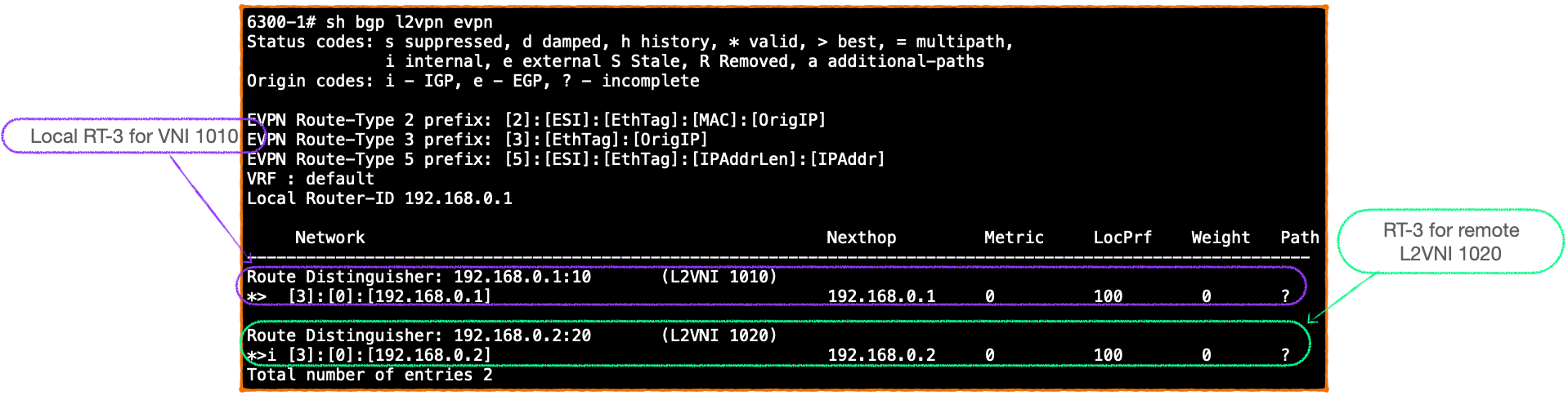
- Here's the BGP EVPN table on 6300-1 at this stage, it consists of just RT-3s for the local L2VNI 1010 and 6300-2's L2VNI 1020.
Additional Config Snippets for Symmetrical IRB
Config Snippet 1: L3VNI
- Symmetrical IRB utilises a concept new to this series of blogs, the L3VNI.
- The L3VNI is configured on all VTEPs that wish to communicate and route between subnets.
- VTEPs forward inter-subnet traffic between each other marked with the L3VNI in the VXLAN header.
- In order to maintain traffic separation across the core, L3VNIs are associated with a customer VRF.
- L3VNIs are configured under the VXLAN interface:
interface vxlan 1
    source ip 192.168.0.1
    no shutdown
    vni 1010
        vlan 10
    vni 5000
        vrf customer_a
        routing
Why do we need the L3VNI?
- With VXLAN bridging and asymmetrical IRB, the packets sent across the VXLAN network are encapsulated with the destination L2VNI.
- The receiving VTEP decapsulates and performs an L2 look up in the VLAN associated with the destination L2VNI only.
- However, with symmetrical IRB, the ingress VTEP is not configured with the destination L2VNI & VLAN information. It is left to the egress VTEP to perform the final routing look up, and determine the destination L2VNI.
- As such, the ingress VTEP cannot encapsulate the traffic with the L2VNI.
- Instead, the L3VNI is used as a shared VNI between all VTEPs that wish to communicate.
- For inter-subnet traffic, the ingress VTEP determines the next hop VTEP and encapsulates the packets with the L3VNI number, in this case, 5000.
- The L3VNI is bound to a VRF, so this keeps the traffic confined to its VRF / VPN as it traverses a shared VXLAN network.
- The egress VTEP, receives this VXLAN traffic and can then perform the necessary VRF-specific routing look up.
- Thus, rather than each VTEP having to be configured with every L2VNI in the network, they are only configured with their own local ones, and one L3VNI for remote, inter-subnet traffic.
Config Snippet 2: VRF-specific BGP IPv4 unicast address-family
To explain why we need to expand the BGP configuration for symmetrical IRB, let's first reflect on asymmetrical IRB.
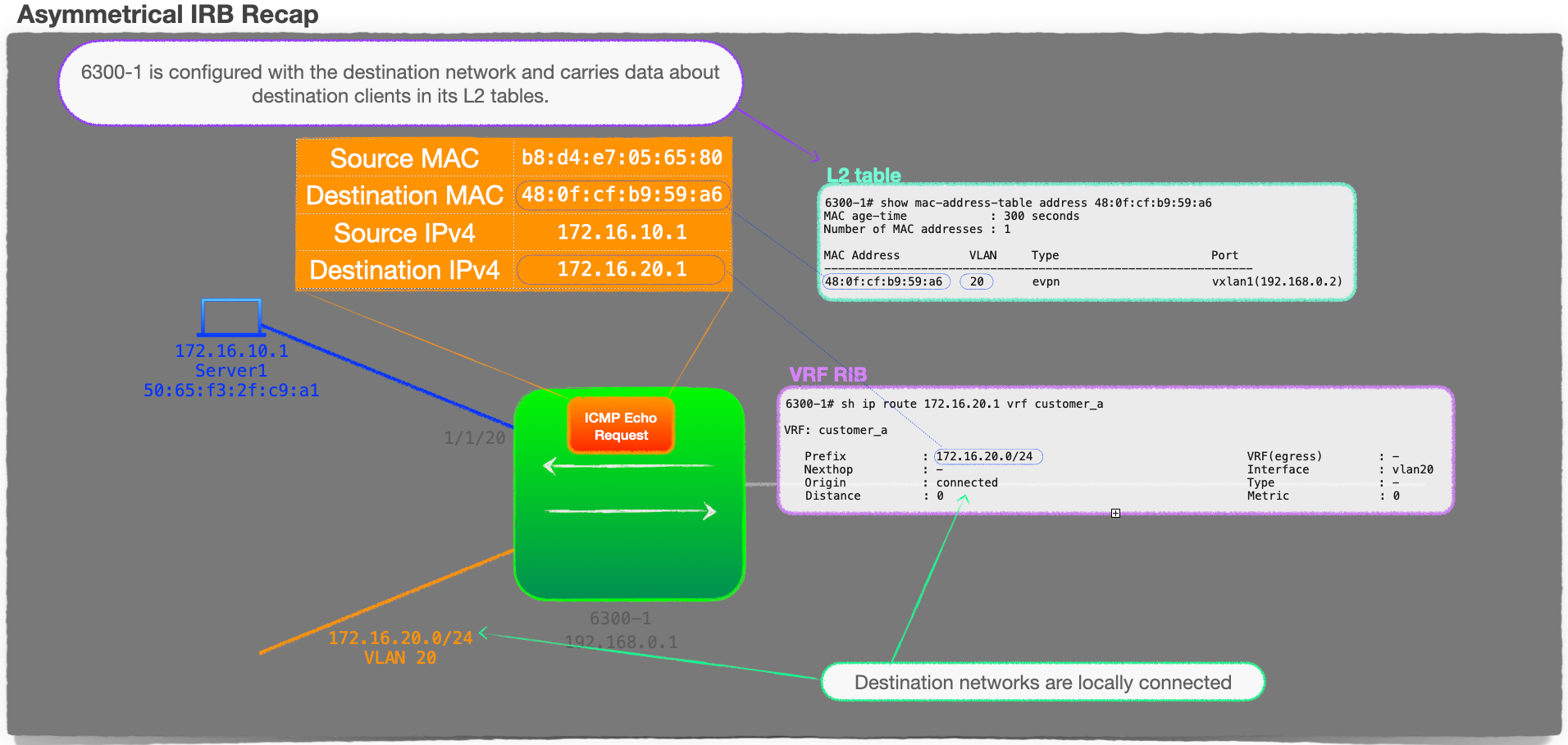
Directly connected routing with asymmetrical IRB
- If you recall from the previous post, with asymmetrical IRB, all of the routing is performed on the ingress VTEP.
- A successful L3 lookup, routing from source subnet to destination subnet, is possible because the VTEPs are configured with all of the subnets that they are required to route between.
- The routing on the ingress VTEP is just an L3 lookup between directly connected subnets!
EVPN routing with symmetrical IRB
- However, with symmetrical IRB, we no longer have this restriction, the subnets do not need to be configured locally, so does our ingress VTEP know about destination subnets?
- The answer is not too dissimilar to standard routing; the VTEPs advertise their local subnets to their peers, and they do this using BGP EVPN.
- But, this is not just standard BGP, so let's break it down:
- Firstly, we need to tell BGP which networks to advertise. These networks are on the customer-side, and, from the VTEP point of view, they are attached to a VRF.
- Thus we need to create a customer VRF-specific BGP table.
- The networks themselves are just IPv4 unicast, so we create that type of address-family under the BGP VRF entry.
- Finally, just like any BGP configuration, we can control the networks that we wish to inject into BGP, using the
network&maskcommand, or we can just redistribute.
Let's put all that together, here's our new config snippet:
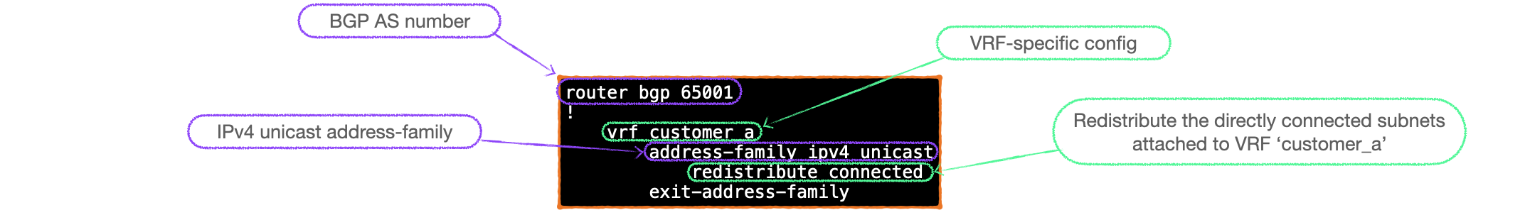
router bgp 65001
!
    vrf customer_a
        address-family ipv4 unicast
            redistribute connected
        exit-address-family
I think it is worth reiterating those steps so here's a graphical summary of the new config:
Not your usual IPv4 unicast
- We should also take note that, with this configuration, there is no neighbour statement within the address-family. We are not advertising networks as standard IPv4 unicast BGP UPDATEs.
- The networks are injected into BGP and advertised using a new type of EVPN Route Type, that being the Route Type 5.
EVPN Route Type 5
- Route Type 5, or RT-5, are for IP Prefix Advertisement.
- They are the subject of RFC 9136, but their operation, in relation to symmetrical IRB, is covered in RFC 9135.
- Whereas RT-2 updates advertise the MAC and, possibly the IP, of a known host; the RT-5 advertises the networks injected into BGP.
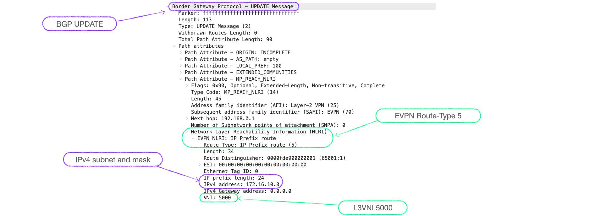
Here's a packet capture of an RT-5, you can see the prefix 172.16.10.0/24 and the L3VNI 5000:
RT-5s in action
- As mentioned, with symmetrical IRB, the destination networks are not configured and, thus, are not directly connected. They must be learnt.
- Route Type 5s allow EVPN peers to advertise their directly connected networks.
- VTEPs install the IP prefixes they learn from VTEP peers via RT-5s in their routing tables.
- Now, when an ingress VTEP receives a packet addressed to a remote network, it refers to the relevant VRF-specific routing table. If there is an entry for the destination subnet, it forwards the packet to the next hop VTEP.
- Upon receipt of the VXLAN packet, the egress VTEP is now prompted to ARP for the destination host, and if successful, the VTEP will generate an RT-2 MAC-IP update for the destination client.
Thus the RT-5 allows the VTEPs to bootstrap the process to generate the MAC-IP RT-2 information that they need for successful traffic flows, using just the IP prefix information.
Config Snippet 3: redistribute host-route
redistribute host-route is configured under the EVPN VLAN like so:
evpn
    vlan 10
        rd auto
        route-target export auto
        route-target import auto
        redistribute host-route
This command helps to ensure traffic follows the best path to a destination client in symmetrcial IRB network, here's how:
Traffic optimization with redistribute host-route
- If multiple VTEPs advertise a destination subnet, it can lead to sub-optimal traffic flows because the subnet is advertised at two or more VTEPs, but a destination host only sits local to one of them.
Let's look at a three VTEP network to illustrate this point:
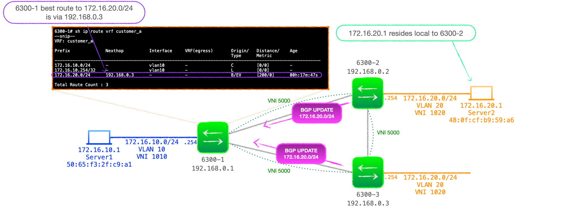
- In the above example, 6300-2 and 6300-3 advertise 172.16.20.0/24, but it is 6300-3's UPDATE that is installed as the best path to 172.16.20.0/24.
- However, 172.16.20.1 actually resides local to 6300-2, not 6300-3.
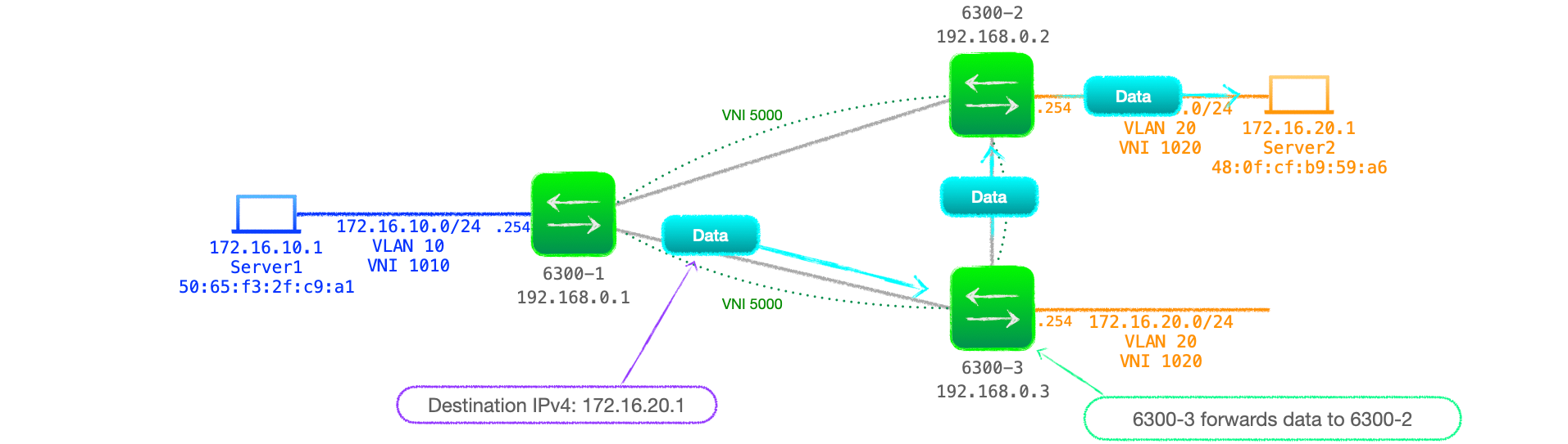
- When 6300-1 routes traffic to 172.16.20.1, it uses its routing table entry, sending the traffic to 6300-3, which then forwards it on to 6300-2! See Figure 7 below.
RT-2 - present but not used
- Despite the RT-5 subnet advertisement causing this sub-optimal flow, the usual EVPN L2VNI is in operation here.
- RT-2s are still generated, but, by default, they are not used.
- For example, in this setup, once the destination client responses to an ARP request, 6300-2 will advertise a MAC-IP RT-2 for 172.16.20.1/32.
- At this point, 6300-1's BGP EVPN table will contain an RT-2 entry for 172.16.20.1, with the correct next-hop of 192.168.0.2, and an RT-5 with the next-hop of 192.168.0.3.
- However, without
redistribute host-route, only the RT-5 is injected into the routing table.
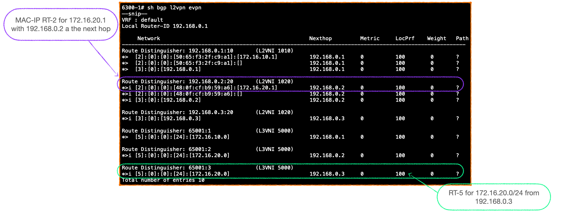
Here's 6300-1's BGP EVPN table, note the RT-2 and the RT-5 entries.
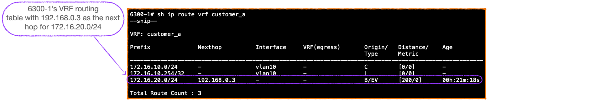
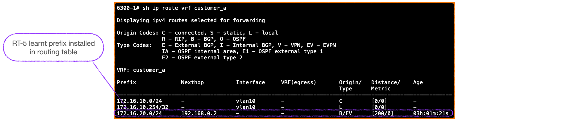
- Here's 6300-1's routing table for VRF 'customer_a'. Only the information from the RT-5 is injected into the RIB. Therefore, 6300-1 uses this to route the traffic on what proves to be a sub-optimal path, to 6300-3, rather than directly to 6300-2:
With 'redistribute host-route'
- To improve the traffic flow, we configure
redistribute host-routeon the advertising VTEP
6300-2# conf
6300-2(config)# evpn
6300-2(config-evpn)# vlan 20
6300-2(config-evpn-vlan-20)# redistribute host-route
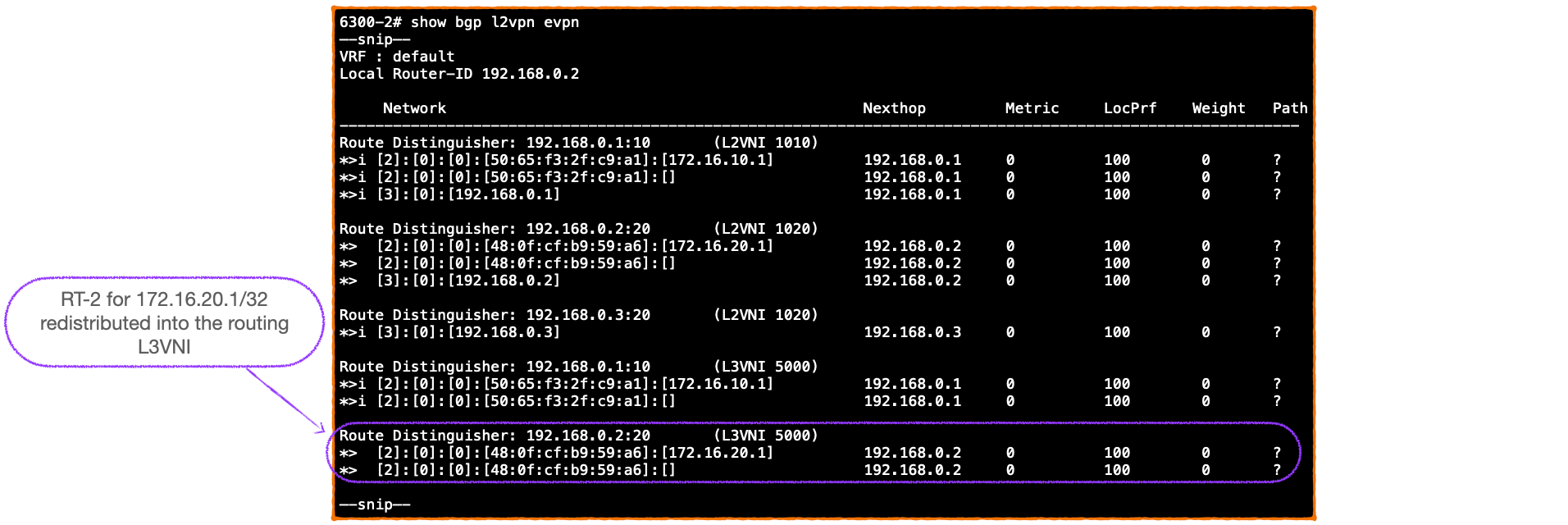
- This redistributes the MAC-IP RT-2 for 172.16.20.1/32 into the routing L3VNI:
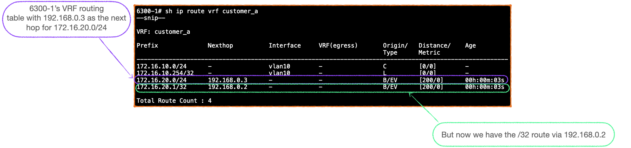
- 6300-1 injects the routes from the L3VNI into its routing table and thus we see the /32 route via 192.168.0.2 in the VRF routing table and our traffic flows are optimized.
A RIB full of /32s???
- To illustrate my point, I'm deliberately using examples with only the minimum of entries.
- But, with networking, it is always wise to ask ourselves, does this scale?
- Having a RIB full of /32s does not seem like good networking. What impact will that have on burning the finite hardware cache resources on our switches?
- Firstly, not all networks automatically need to redistribute the /32s. If subnets are not stretched across multiple sites and advertised by multiple VTEPs, then the RT-5 and RT-2s will always align.
- But, with any site utilising client migration, moving VMs from site to site, subnets are going to be stretched, and thus we have our /32s populating the RIBs.
In light of this issue, recent releases of Aruba AOS-CX utilise FIB optimization so that only active traffic flows for EVPN learnt routes are passed from the RIB to hardware forwarding.
This is a new feature as of AOS-CX 10.10, I'll cover it in a future post.
Config Snippet 4: Virtual-MAC address
- Finally, each VTEP must be configured with a virtual MAC address that has to be unique within any particular network.
- Here's an example:
virtual-mac 00:00:00:aa:bb:11 - This piece of config is also know, in RFC 9135, as the 'EVPN Router's MAC', and it is advertised by VTEPs as a BGP extended community in their EVPN UPDATEs.
- Along with Route Type 5s, it is another new piece of the puzzle that is vital to the successful operation of symmetrical IRB. Here's why:
EVPN Router's MAC and why it is needed?
- Once again, this is another component that is necessary because the symmetrical IRB VTEP is not configured with the destination subnets that it must route to.
- The ingress VTEP does not have any insight into the destination Layer 2 domain that it must route to, and so, does not have any knowledge of the destination MAC address for the customer-side client. This is the destination MAC in the inner header of an encapsulated VXLAN packet.
- Instead, the ingress VTEP addresses the inner header to the egress VTEP at L2, and uses the egress VTEP's Router MAC as the address in question.
- The egress VTEP decapsulates the incoming VXLAN header, removes the outer header to reveal the inner header, addressed to its own virtual-MAC.
- The egress VTEP can then continue the routing process with an IP and then a MAC lookup.
We will cover this in depth later as part of the full walkthrough, please see the 'Symmetrical Walk Through' in the next section.
EVPN Router's MAC Packet Captures
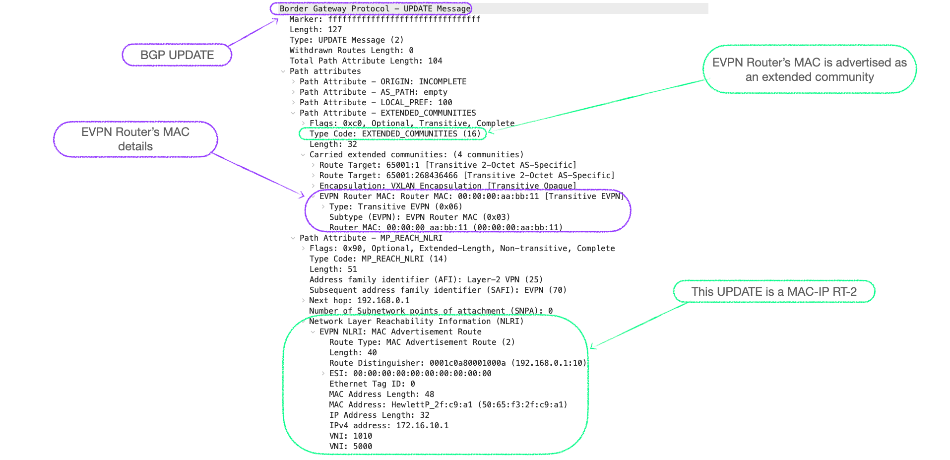
Here's a packet capture of a BGP EVPN RT-2 UPDATE in a symmetrical IRB design, that shows the EVPN Router's MAC of 00:00:00:aa:bb:11 being advertised:
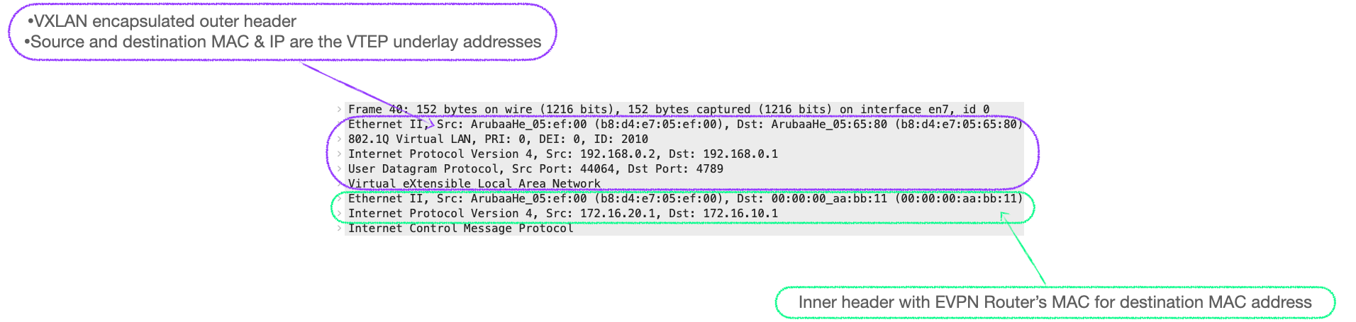
Here's a capture of an ICMP Echo Request as it traverses the VXLAN network. We can see the EVPN Router's MAC is the destination MAC in the inner header.
With this information in mind, let's have a detailed look at the control plane and data plane processes involved in symmetrical IRB.
🚶Symmetrical Walk Through
🕹 Control Plane
Base line
- To start, both 6300-1 and 6300-2 are fully configured for EVPN symmetrical IRB with an established BGP session.
Here's the config from 6300-1 again, with the added config snippets:
hostname 6300-1
!
vrf customer_a
    rd 65001:1
    route-target export 65001:1 evpn
    route-target import 65001:1 evpn
!
vlan 1,10,2010
virtual-mac 00:00:00:aa:bb:11
evpn
    vlan 10
        rd auto
        route-target export auto
        route-target import auto
        redistribute host-route
!
interface 1/1/10
    no shutdown
    description vxlan_int
    no routing
    vlan trunk native 1
    vlan trunk allowed 2010-2011
!
interface 1/1/20
    shutdown
    no routing
    vlan trunk native 1
    vlan trunk allowed 10
!
interface loopback 0
    ip address 192.168.0.1/32
    ip ospf 1 area 0.0.0.0
!
interface vlan 10
    shutdown
    vrf attach customer_a
    ip address 172.16.10.254/24
!
interface vlan 2010
    ip address 10.0.0.0/31
    ip ospf 1 area 0.0.0.0
    ip ospf network point-to-point
!
interface vxlan 1
    source ip 192.168.0.1
    no shutdown
    vni 1010
        vlan 10
    vni 5000
        vrf customer_a
        routing
!
router ospf 1
    router-id 192.168.0.1
    area 0.0.0.0
router bgp 65001
    bgp router-id 192.168.0.1
    neighbor 192.168.0.2 remote-as 65001
    neighbor 192.168.0.2 update-source loopback 0
    address-family l2vpn evpn
        neighbor 192.168.0.2 activate
        neighbor 192.168.0.2 send-community both
    exit-address-family
!
    vrf customer_a
        address-family ipv4 unicast
            redistribute connected
        exit-address-family
- Both VTEPs have their customer-side interface, 1/1/20, shut.
- At this starting stage, there are no RT-2s.
- I've also shut the VLAN interface for VLAN 10 on 6300-1 and VLAN 20 on 6300-2 so that no RT-5's are generated.
Steps
- We start by raising the VLAN interface 10 on 6300-1 with the
no shutcommand. - The 172.16.10.0/24 prefix is installed into 6300-1's VRF routing table for 'customer_a' as a connected network, and, as such, is redistributed into BGP EVPN, generating a Route Type 5.
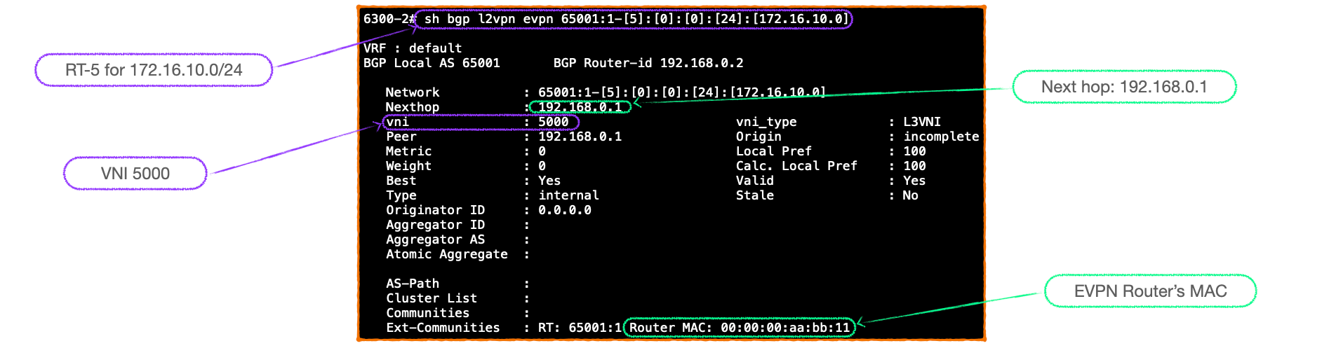
- 6300-1 advertises this RT-5 for 172.16.10.0/24 to its BGP EVPN peer, 6300-2, which checks the route-targets and installs it in its BGP EVPN table, and routing table. Here's a closer look at the RT-5, note the advertisement of 6300-1's virtual-mac:
- We now perform the same steps on 6300-2, raising the VLAN interface for VLAN 20; 172.16.20.0/24 is installing in the RIB and redistributed into BGP EVPN, then advertised as an RT-5.
- At this point, 6300-1 and 6300-2 have BGP EVPN tables populated by RT-3s and RT-5s only:
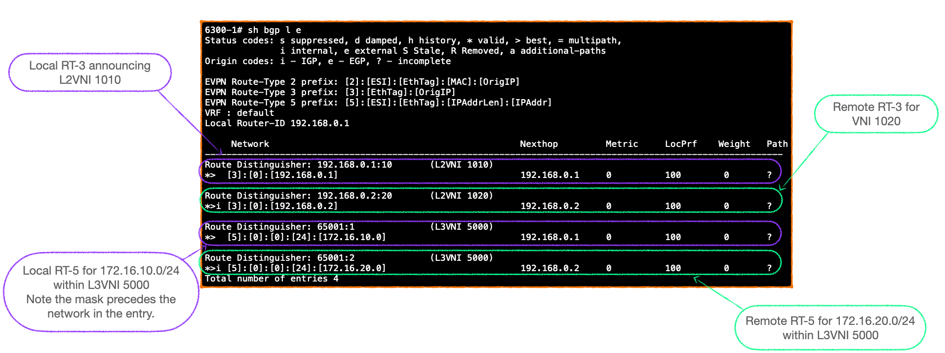
- The RT-5 prefixes are imported into the VRF RIBs of the receiving VTEPs as routes learnt via EVPN:
- Next, we open 6300-1 customer-facing interface, Server1 GARPs, creating an entry for its MAC address in the VTEP's L2 table; which generates a MAC only RT-2 that 6300-1 advertises to its VTEP peers.
- We do the same on 6300-2, resulting a state where the pair of VTEPs have EVPN tables populated by MAC only RT-2s, RT-3s and RT-5s.
This is where we will end our look at the control plane and move on to the data plane.
Data Plane
Now let's dive into the traffic exchange processes required to allow Server1 to ping Server2.
I've split this into two sections:
- Firstly, the preample, contains the steps required when a VTEP only has an RT-5 to route to the destination VTEP. This is akin to the first packet sent.
- Secondly, we look at the data plane processes when the ingress VTEP has use of a MAC-IP RT-2 after the first packet exchange of the preamble.
**In an effort to mollify the networking purists amongst my valued readership I concede that the preamble is not just a data plane process, but does indeed include control plane exchanges. I hope you will forgive me this indiscretion in the name of educational purposes. I think the process is complex enough to merit a full examination in this manner. *
Preamble - Ingress VTEP routes via RT-5
There's a lot going on here so let's reconfirm the starting point.
- 6300-1 and 6300-2 have an established BGP EVPN session.
- Both VTEPs are configured with
redistribute host-routeunder their local attached VLAN. - The customer-serving port and interface are up.
- Both VTEPs have received GARP from their local client.
- This means we start with BGP EVPN tables populated with RT-5s and MAC only RT-2s.
- It follows that the prefixes learnt via RT-5 are injected into the VRF-specific routing tables, but the MAC only RT-2 merely sit in the BGP EVPN table.
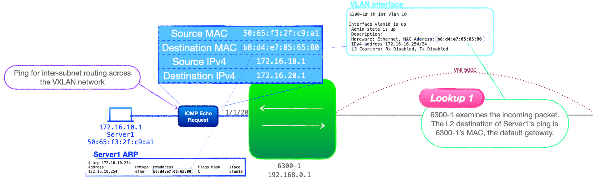
- Server1 pings Server2; it sends an ICMP echo request with a destination IP address of 172.16.20.1 and a destination MAC address of 6300-1's VLAN 10 interface.
- 6300-1 receives the frame, checks the destination MAC and observes that it is addressed to itself.
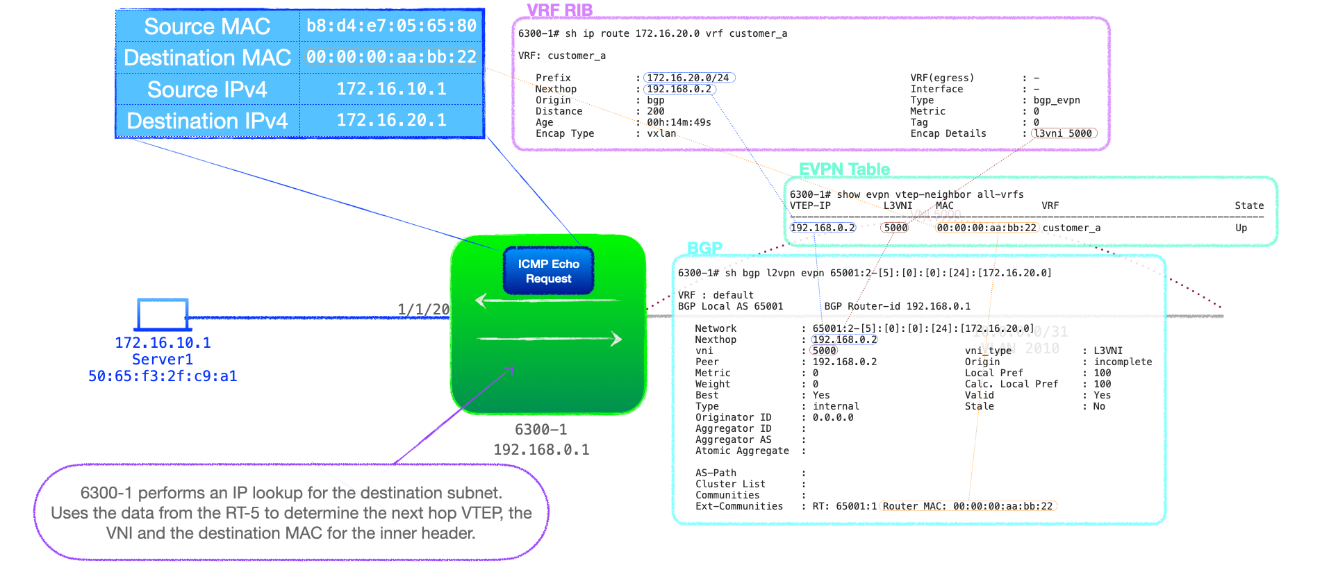
- 6300-1 consults the routing table bound to VRF 'customer_a' and discovers an entry for 172.16.20.0/24, learnt via an RT-5 UPDATE, with a Next-Hop of 192.168.0.2, that being 6300-2.
- This look up will also provide 6300-1 with additional information carried in the RT-5:
- VXLAN as the encapsulation type.
- The L3VNI number of 5000.
- The destination MAC address for the inner header, learnt via the EVPN Router's MAC extended community
00:00:00:aa:bb:22.
- For completeness, note that the action of Server1 sending traffic via 6300-1, enables 6300-1 to populate its VRF 'customer_a' ARP cache with Server1's MAC-IP and advertise this to 6300-2.
- 6300-2 receives the VXLAN packet, addressed to itself in the outer-header. When the packet is decapsulated the inner header destination MAC address is also addressed to 6300-2, that being the advertised EVPN Router MAC, 6300-2's virtual-mac.
- 6300-2 checks the inner header destination IP address, 172.16.20.1 and performs an IP routing table look up to reveal that 172.16.20.0/24 is a directly connected network.
- But with no ARP entry for 172.16.20.1, 6300-2 initiates the ARP resolution process, broadcasting an ARP request on 172.16.20.0/24.
- Server2 responds to the ARP request, 6300-2 populates its VRF ARP cache with the MAC-IP entry and generates a MAC-IP RT-2, which is advertised to 6300-1.
- 6300-2 now checks its MAC address table for Server2's MAC and forwards the packet out of the relevant port.
Data Plane Process - Ingress VTEP routes via MAC-IP RT-2
We now move on to the processes involved if the ingress VTEP has an RT-2 entry for 172.16.20.1, and is configured to redistribute the /32 entries into its RIB.
- 6300-1 receives a packet from 172.16.10.1 to 172.16.20.1. 6300-1 performs an L2 lookup and discovers that the packet is addressed to its own L2 address for VLAN 10, that being 172.16.10.1's default gateway. This is a MAC look up. Look up 1
- 6300-1 knows that it needs to route the traffic and consults its routing table bound to VRF 'customer_a'. The VTEP has received a RT-2 for this destination and, thus, finds a /32 entry for 172.16.20.1, via 192.168.0.2. This is an IP look up. Look up 2
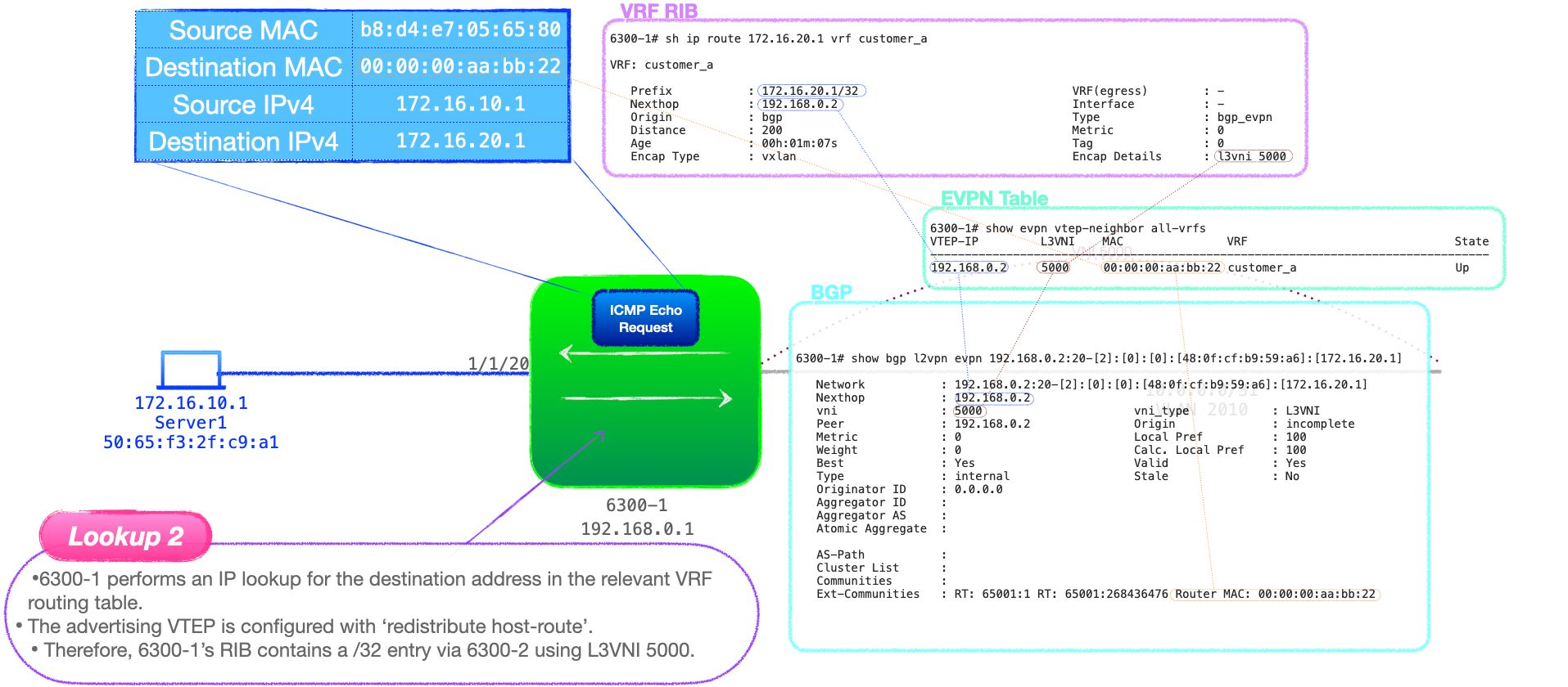
- 6300-1 encapsulates packet and forwards to 6300-2. The destination MAC address in the inner header is the EVPN Router's MAC address, learnt via the BGP UPDATE extended community, advertised by 6300-2.
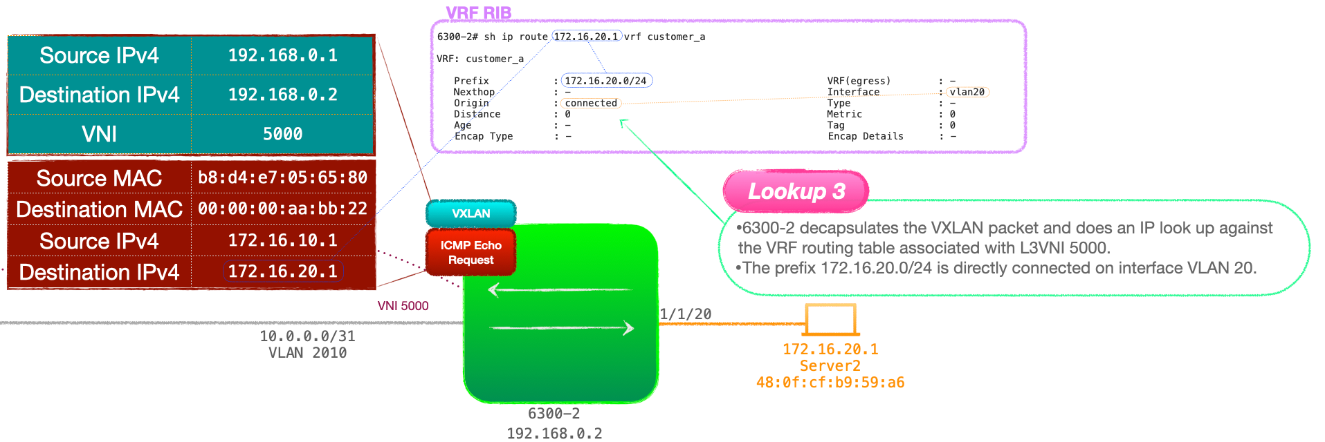
- 6300-2 decapsulates the VXLAN packet and uses the VNI to identify which VRF routing table to consult.
- 6300-2 checks the RIB bound to VRF 'customer_a' and learns that the destination network, 172.16.20.0/24 is directly connected. This is an IP look up. Look up 3
- 6300-2 checks its ARP cache to find the destination MAC address for 172.16.20.1.
- 6300-2 then consults its MAC address table for the outgoing port associated with Server2's MAC address. This is a MAC look up. Look up 4.
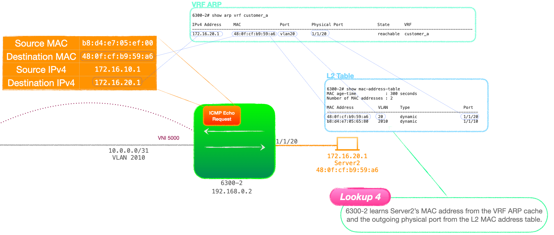
- Finally 6300-2 forwards the packet out of the port in question.
- When Server2 responses with its own ICMP Echo Reply, we have a successful ping.
So why it is called 'symmetrical'?
Here's those look ups again
- Ingress VTEP: MAC then IP
- Egress VTEP: IP then MAC
The look ups are mirrored on the VTEPs, they are symmetrical.
"It's like poetry, it rhymes"
Closing Words
Now I've covered the main topics of EVPN, I'm going to proceed by turning this into video content, plus I will return with further posts focused on specific aspects of EVPN networks.
Thanks for reading.
🐦@joeneville_
💬Final note: There is so much in here that I've no doubt there are typos and errors, if you see anything glaring, please let me know via twitter or joenullzero@gmail.com